Water pumps are one of the most common backup-power mistakes. The buyer adds up the running kW, buys a UPS of that size, and the UPS trips the first time the pump starts. The pump is not the problem; the starting current is.
This guide explains how a pump start changes the sizing, when a UPS is the right tool, and how to specify a system that actually carries the load.
Why is a pump harder to back up than an IT load?
An IT load is relatively constant and has a high power factor. A pump motor is the opposite:
- Starting current: 5–7 times rated at direct-on-line start.
- Power factor: lower at start and at part load.
- Duty cycle: the pump may start and stop several times an hour.
- Environment: wet, dusty, hot, or remote.
A UPS sees the starting current as an overload. If the UPS does not have the overload rating and the bypass coordination, it transfers to bypass or trips, and the pump stops anyway.
How do you calculate the real demand?
Start from the pump nameplate and the duty point.
- Rated motor power: kW or HP on the nameplate.
- Service factor: the motor may run above nameplate; use the service-factor kW.
- Starting method: direct-on-line, star-delta, soft starter or VFD.
- Starting current: from the motor datasheet, not a generic multiplier.
- Power factor and efficiency: to convert to kVA.
- Simultaneous pumps: how many start together or in sequence.
For a 7.5 kW motor at 0.82 power factor and 0.9 efficiency, the running input is about 10.2 kVA. At direct-on-line start, the apparent power can be 5–7 times that for a few seconds. A UPS must either ride through that or the starting method must change.
UPS, inverter or generator: which one?
The right answer depends on what must keep running.
| Requirement | Best tool | Why |
|---|---|---|
| Pump controls, sensors, telemetry | Small online UPS | Clean power, 0 ms transfer, low load |
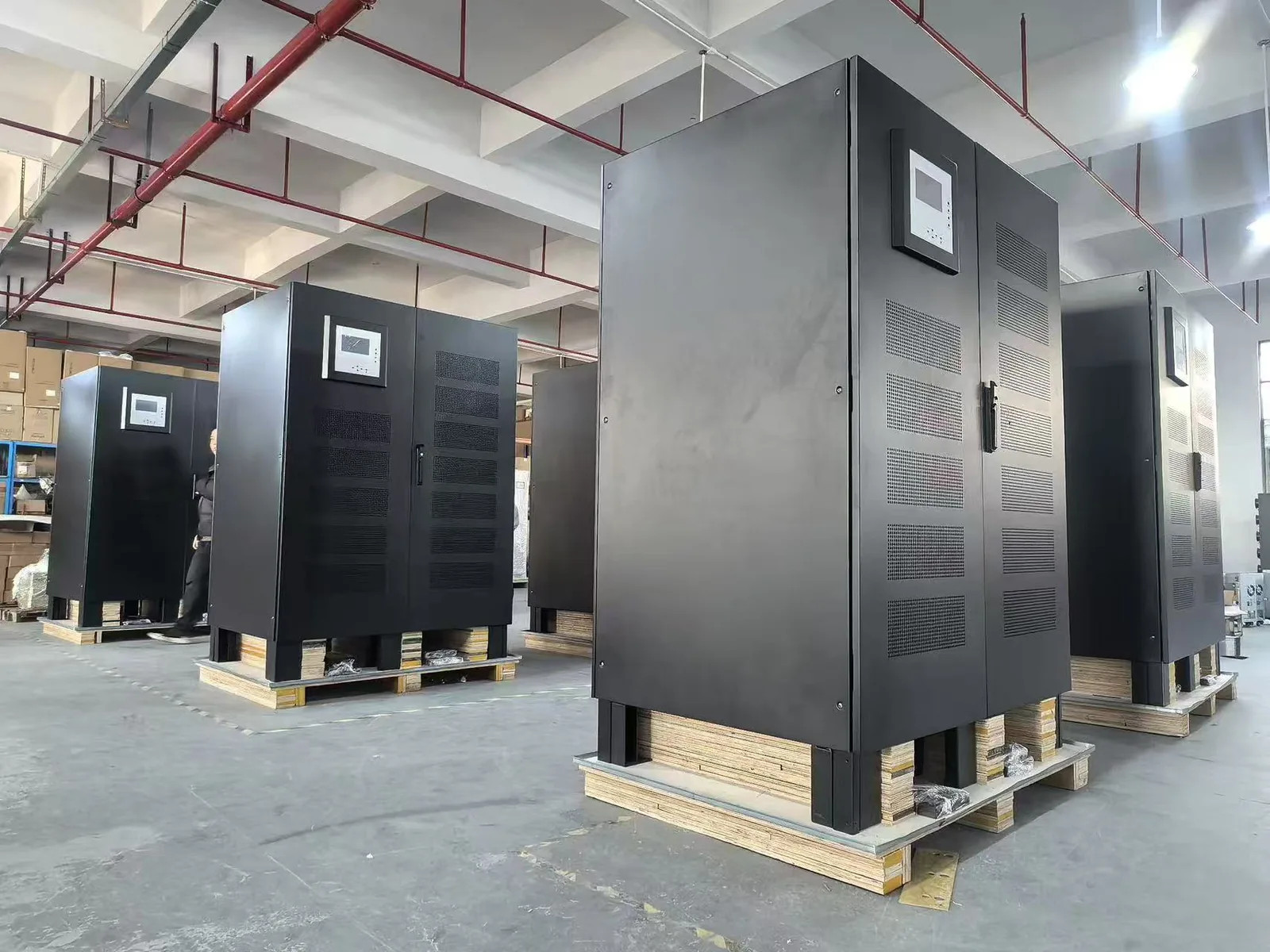
| Pump motor, short outage | Industrial UPS with high overload | Must ride through the start |
| Pump motor, long outage | Generator + soft starter/VFD | Fuel is cheaper than batteries |
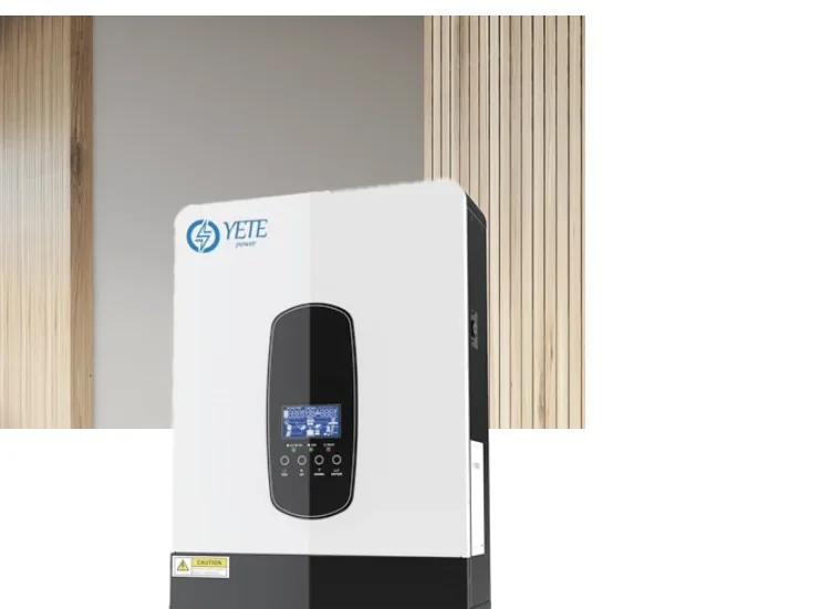
| Remote borehole, no generator | Solar inverter + battery | DC source and MPPT charging |
| Wide voltage swings | AVR at the incoming supply | Protects the motor and controls |
For a booster set in a building, the usual design is a small UPS for the controller and a generator for the pump. For a remote borehole, a solar inverter with a battery is often more practical than a UPS.
What does a pump backup configuration look like?
| Site | Pump | Starting method | Backup |
|---|---|---|---|
| Building booster set, 2.2–7.5 kW | 1–2 pumps | Soft starter | 5–10 kVA UPS for controls + generator |
| Process pump, 15–45 kW | 1 pump | VFD | Industrial UPS 20–60 kVA for ride-through |
| Remote borehole, 2.2–5.5 kW | 1 pump | VFD or direct | Solar inverter 5–8 kVA + battery |
| Lift station, 7.5–30 kW | 2 pumps, alternating | Soft starter | Generator + UPS for controls |
| Irrigation, 11–37 kW | 1–3 pumps | Soft starter | Generator, AVR optional |
The table is a starting point. The final size depends on the measured starting current, the pump curve and the runtime target.
What about the battery and the runtime?
A pump that runs for hours on battery needs a very large bank. For a 15 kW load and 2 hours at a 384 VDC bus, 0.85 inverter efficiency and 0.6 depth of discharge, the estimate is about 153 Ah. That is a large, heavy, expensive bank, and the charger must be sized to recharge it.
For most pump sites, the battery should cover the generator start, a controlled stop, or a short ride-through. Long runtime is a generator decision, not a battery decision.
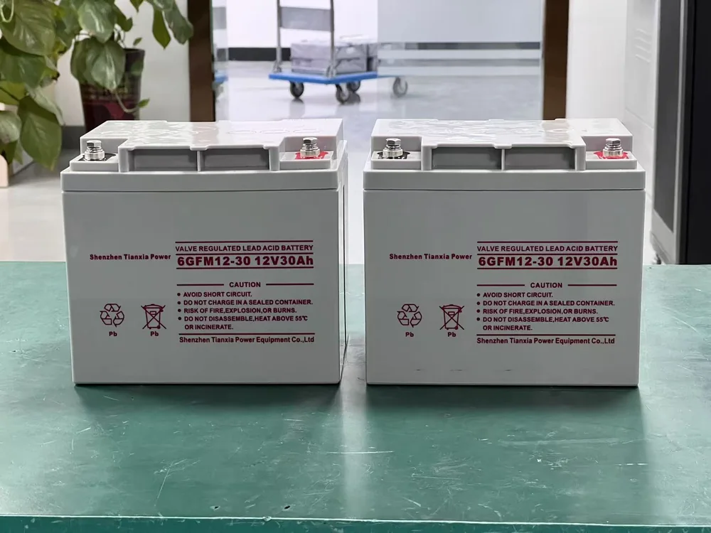
If the pump is in a remote location, a solar inverter with a lithium battery and MPPT charging may be more practical. The battery must be rated for the ambient and the cycle count.
What should be in the specification?
A pump backup specification should state:
- The pump model, rated kW, service factor, head and flow.
- The starting method and the measured starting current.
- The number of pumps and the simultaneity.
- The runtime target and the generator start time.
- The input voltage, phase and frequency.
- The AVR requirement and the input voltage window.
- The enclosure rating and the installation environment.
- The communication interface (RS485, MODBUS, dry contact, SNMP).
Do not accept a quote that lists only “10 kVA UPS for pump”. The starting current and the starting method decide whether the system works.
Which standards and documents apply?
The UPS is specified to IEC 62040-1/-2/-3. The motor and the installation follow local electrical codes and the pump manufacturer’s requirements. An AVR is specified to IEC 61558-1 and the relevant voltage-regulation standard. The battery follows IEC 60896-21/-22 for VRLA or IEC 62619 for lithium.
Ask for the model datasheet, the starting-current compatibility statement, the battery configuration sheet and the test report. The pump supplier should confirm the starting current and the allowable voltage dip.
Next step
Send the pump nameplate, the starting method, the measured starting current, the number of pumps, the runtime target and the site voltage. We will return the UPS or inverter size, the battery configuration and the generator interface.
Start with the industrial UPS page, compare the three-phase range, or use the sizing calculator for a first estimate.